
Home / Services / MEP Shop Drawing Services
MEP Services · Shop Driving
MEP Shop Drawing Services And HVAC Duct Shop Drawings For US Projects
Shop drawings are where design meets the real world. They show how a system will actually be built: exact routing, fittings, hangers, elevations and connection points. And they’re usually needed fast, with submittals due and installation crews waiting.
What Are MEP Shop Drawings?
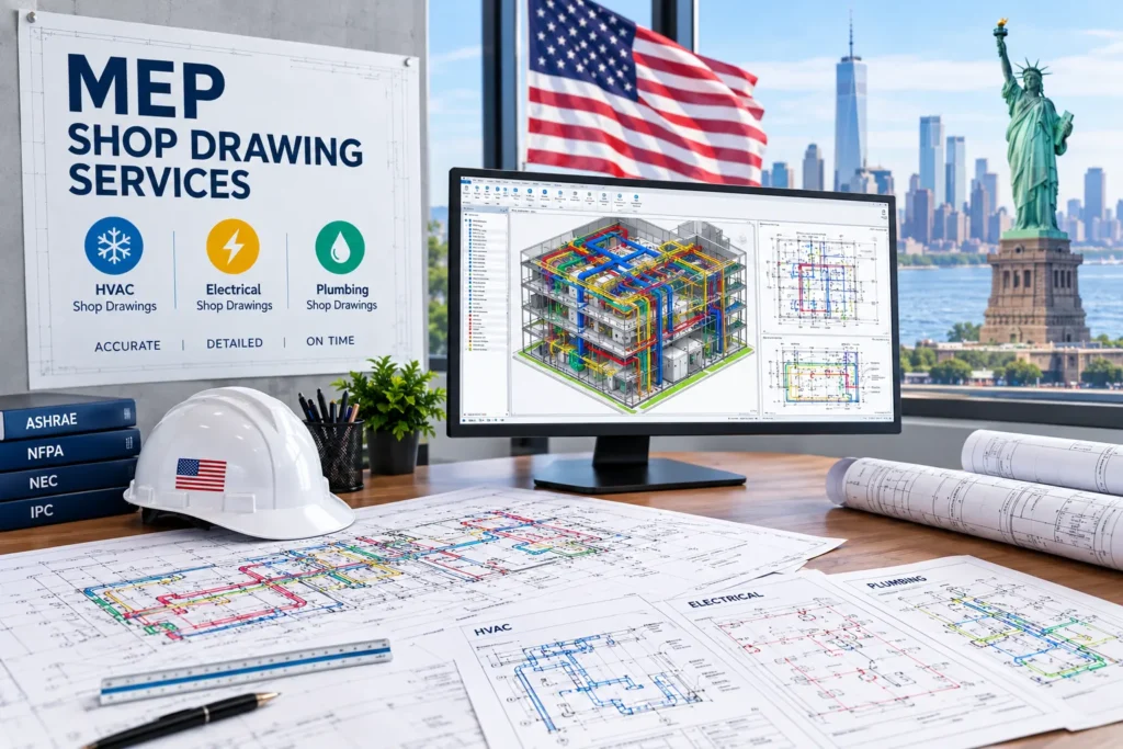
MEP shop drawings are detailed, trade-specific drawings prepared by a contractor or fabricator to show how mechanical, electrical, plumbing and fire protection systems will be fabricated and installed. They interpret the engineer’s design drawings and turn them into something a shop or a crew can build from.
On most US projects, shop drawings go through a submittal process. The general contractor reviews them, the architect and engineer of record review them, and comments come back for correction. A clean, well-organized set gets through that process faster.
MEP Shop Drawings Versus Coordination Drawings
The two are often confused. Coordination drawings show how trades share the space: who goes where, at what elevation. Shop drawings show how each trade builds its own work inside that agreed layout. Good shop drawings come after coordination, and we recommend never skipping the coordination step. Ask us about our BIM coordination service if you haven’t done it yet.
Ductwork
HVAC Duct Shop Drawings
Ductwork is the most common shop drawing request we receive, and for good reason. It’s large, it’s expensive to remake, and small errors turn into cutting on site.
Our HVAC duct shop drawings show dimensioned plans, sections and elevations with duct sizes, centerline or bottom-of-duct elevations, transitions, offsets, turning vanes, dampers, access doors, flexible connections and equipment connections. Ductwork is broken into shippable sections with joint types, gauges and reinforcement noted in line with SMACNA standards. Where your shop uses fabrication software, we can prepare the model and drawings so they export cleanly.
- Rectangular, round and flat-oval ductwork
- Spiral duct and fittings
- Grease duct and kitchen exhaust to NFPA 96 requirements
- Stainless steel and specialty exhaust for labs
- Insulation and liner thickness shown
- Duct hangers, supports and seismic bracing locations where required
Scope
MEP Shop Drawing we prepare
Piping Shop Drawings
Chilled water, hot water, condenser water and steam Refrigerant and glycol piping Medical gas and process piping Pipe spool sheets with cut lengths and weld or joint locations
01
Plumbing Shop Drawings
Domestic water supply, sanitary waste and vent, storm drainage Riser diagrams and fixture connection details Plumbing sleeves, floor drains and cleanouts
02
Electrical Shop Drawings
Conduit and cable tray routing Busway and feeder layouts Electrical room and equipment layouts Underslab and in-slab conduit layouts
03
Fire Protection Shop Drawings
Sprinkler mains, cross mains and branch lines Standpipes, fire pump rooms and riser assemblies Sleeve and penetration drawings for fire-rated assemblies
04
General MEP Drawings
Equipment room layouts and housekeeping pad plans Hanger and support layouts Sleeve, insert and wall penetration drawings Trade coordination sheets and slab opening drawings
05
Industries & project types
What A Proper Shop Drawing Set Contains
- Plans referenced to grid lines, room names and north arrow
- Section views wherever systems stack or cross
- Dimensions tied to structure so installers can lay out from the slab
- Elevations to bottom or centerline of duct, pipe or conduit
- Equipment tags, system labels and flow directions
- Keynotes, legends and general notes
- Revision clouds and a revision log
- Coordination status noted between trades
We work with mechanical contractors, sheet metal shops, HVAC design-build firms, mechanical and MEP engineers, general contractors, construction managers and owners’ representatives. If your in-house team is stretched, we slot in as an extension of it and follow your workflows.
Submittal Process
Built For The Submittal Process
We format sets to your submittal requirements, with clear sheet numbering, consistent title blocks and a revision log that lets reviewers see exactly what changed between issues. Sheet sizes are ANSI D or ARCH D unless you prefer otherwise.
Shop drawings are construction documents, not design documents. Where your contract or local rules require review or a seal from a licensed professional engineer, that stays with your team. We prepare the drawings and support any comments that come back
Our process
Our MEP Shop Driving process
Six steps from first drawing review to final delivery — with revisions tracked in a clear log and rolled into the model every cycle.
Step 1
Kickoff
Review of design drawings, specifications, submittal requirements and equipment submittals.
Step 2
Modeling
System built or updated in Revit to LOD 350–400.
Step 3
Coordination
Clashes resolved with other trades before drawings are produced.
Step 4
Drawing Production
Plans, sections, details and schedules generated from the model.
Step 5
QA/QC
Dimensions, tags, sheet index and standards checked.
Step 6
Submittal Support
Revisions completed based on comments from the GC, architect and engineer.
Standards And Formats
We draw to SMACNA duct construction standards, ASHRAE guidance, NFPA requirements for fire protection, the NEC for electrical, and the plumbing and mechanical codes adopted in your jurisdiction. Deliverables include PDF and DWG sheets, with Revit files, fabrication exports and BOM schedules available if required.
Typical Turnaround And What Affects It
Turnaround depends on building size, system density, and how complete the design and coordination are. A single floor of ductwork can take a few days, while a full hospital wing takes longer. Late design changes and missing equipment submittals are the two biggest causes of delay, so send those early. We’ll give you a schedule before starting and update it if the scope changes.
Why BIMACME
Why Contractors Choose Bimacme For Shop Drawings
If you have outsourced MEP BIM before, you know the risks: slow replies, drifting standards, models you have to rebuild. We set things up to avoid that.
- Drawings come from a coordinated model, not from guesswork
- Sets that reflect how US crews install, hang and sequence
- Flexibility to take on peak workloads without long-term commitment
- Quick revisions during the submittal cycle
- Support for fabrication, prefabrication and field layout
FAQ
Frequently Asked Questions
Still have a question about scope, standards, or staffing? Our team will answer within one US business day.
What Is The Difference Between Coordination Drawings And Shop Drawings?
Coordination drawings show how trades fit together in the space. Shop drawings show how each trade will build and install its own work. Shop drawings come after coordination.
Can You Produce HVAC Duct Shop Drawings From Design Drawings Only?
Yes. We model the duct system from design drawings, coordinate it, then generate the shop drawings from the model.
Do Your Drawings Work With Our Sheet Metal Fabrication Software
We can prepare models and exports to suit common fabrication tools. Tell us what your shop uses at the start.
How Long Does A Shop Drawing Package Take?
It depends on size, complexity and how complete the design is. We give a schedule before starting.
Can You Handle Revisions After The Architect's Comments?
Yes. Reasonable revision rounds are normally part of the agreed scope.
Do You Prepare Fire Sprinkler Shop Drawings?
We prepare layouts and drawings from the design. Hydraulic calculations and submission remain with the licensed fire protection designer or engineer.
What Sheet Sizes And File Formats Do You Deliver?
ANSI D or ARCH D by default, as PDF and DWG. Revit and other formats on request.
Can You Also Produce Spool Drawings?
Yes. Pipe spools with cut lengths, part tags and joint locations are covered in our prefabrication modeling service.
Submittals due soon?
Send us your model or design set and we’ll confirm timing and pricing.