
Home / Services / BIM Coordination
MEP Services · Autodesk Revit
Electrical BIM Modeling Services For US
Electrical work gets squeezed. By the time electricians reach the ceiling, ductwork and piping have already taken the good routes, and a conduit run that looks fine on a 2D plan has nowhere to go.
The fundamentals
What Is Electrical BIM Modeling?
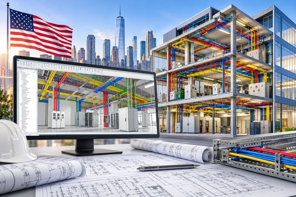
Electrical BIM modeling is the process of creating a 3D model of a building’s electrical systems, including equipment, raceways, devices and fixtures, inside BIM software. Unlike 2D plans that show homeruns and symbols, the model shows real conduit routes, real bends and offsets, real support locations and real equipment clearances.
For an electrical contractor, that means fewer field surprises, better takeoffs and material that arrives labeled and ready for the crew.
Scope
Electrical BIM Modeling services we offer
HVAC Modeling
Utility service entrance and metering Medium and low-voltage switchgear, switchboards and transformers Panelboards, MCCs, disconnects and VFDs Feeders, branch circuit conduit, busway and cable tray Generators, automatic transfer switches, UPS and battery rooms
01
Lighting And Controls
Light fixtures, emergency lighting and exit signs Dimming and lighting control panels Occupancy and daylight sensors Coordination with architectural ceilings and mechanical air devices
02
Fire Alarm And Life Safety
Fire alarm control panels, detectors, pull stations and notification appliances Emergency communication and mass notification Conduit and cable pathways coordinated with fire protection piping
03
Low Voltage And Communications
Structured cabling pathways, cable tray and J-hooks Security, access control and CCTV devices AV, nurse call and paging systems Telecom rooms and rack layouts
04
Site And Grounding
Underground duct banks, manholes and handholes Site lighting and parking lot electrical Grounding, lightning protection and rooftop equipment
05
Built Around The National Electrical Code
Working space in front of electrical equipment isn’t optional. NEC Article 110 sets required clearances for safe operation and maintenance, and a model that ignores them creates problems at inspection. We model working clearances and dedicated equipment space as volumes, so coordination catches conflicts before wire is pulled.
Conduit routing, box locations, separation of different voltage systems and equipment access are modeled in line with your design and the NEC edition adopted in your state. The engineer of record remains responsible for design decisions and calculations. We model faithfully, and we raise questions when the drawings don’t line up.
From Design Intent To Installable Conduit
Many electrical drawings show symbols and homeruns, not actual raceway routes. We develop that design intent into modeled conduit and cable tray with real bends, offsets and supports. Where prefabrication makes sense, we break runs into racks and assemblies with tagged parts and cut lists, ready for your shop.
Levels of development
Levels Of Development For Electrical Models
We follow the BIMForum Level of Development specification, which most US projects use, and agree the LOD for each system in writing before modeling starts.
LOD | Electrical Content | When To Use |
|---|---|---|
LOD 200 | Equipment and main routes, approximate sizes | Early coordination and budgeting |
LOD 300 | Accurate feeders, cable tray, panels, devices and fixtures | Coordination and permit sets |
LOD 350 | Adds supports, junction boxes and interfaces with other trades | Detailed trade coordination |
LOD 400 | Full conduit routing, fittings, racks and assembly detail | Shop drawings and prefabrication |
LOD 500 | Field-verified as-built model with equipment data | Closeout and facility management |
Our process
Our Electrical BIM Modeling process
Six steps from first drawing review to final delivery — with revisions tracked in a clear log and rolled into the model every cycle.
Step 1
Drawing & Spec Review
Review of electrical drawings, single-lines, riser diagrams and specifications.
Step 2
Model Setup & Standards
Setup of the model with your template, worksets and naming conventions.
Step 3
Equipment & Feeder Routing
Equipment placement, followed by feeder and branch conduit routing.
Step 4
Device & Fixture Coordination
Devices and fixtures placed and coordinated with ceilings, ductwork and piping.
Step 5
Multi-Trade Clash Checks
Internal clash checks with mechanical, plumbing, fire protection and structural elements.
Step 6
Final Delivery & Reporting
Delivery of coordinated model, drawings, schedules and clash reports, with all revisions logged.
Cost and TurnAround
What Affects Cost And Turnaround?
Electrical models take longer when the drawings show symbols and homeruns rather than routed conduit, when the LOD is high, or when the design changes often. Repetitive buildings such as hotels and multifamily projects go faster once the first typical floor is set up.
Share your drawings and we’ll quote the assumptions listed.
Why BIMACME
Why choose BIMACME for Electrical BIM Modeling
If you have outsourced MEP BIM before, you know the risks: slow replies, drifting standards, models you have to rebuild. We set things up to avoid that.
- Team that reads US electrical drawings and understands NEC layout issues
- Coordination experience with mechanical, plumbing and fire protection
- Flexible support from a single project to a dedicated modeler
- Confidential handling of your files
- Clean handover that works with your fabrication and layout tools
FAQ
Frequently Asked Questions
Still have a question about scope, standards, or staffing? Our team will answer within one US business day.
Can You Model Electrical Systems From A Single-Line Diagram?
We can build the model from single-lines, plans and specifications. Where information is missing, we log RFIs instead of guessing.
Do You Model Conduits At LOD 400?
Yes. LOD 400 includes exact conduit routing, fittings, supports and rack layouts for fabrication and prefabrication.
Does Electrical BIM Include Low-Voltage Systems?
It can. Data, security, fire alarm, AV and nurse call pathways are often included, especially on coordination-heavy projects.
Will The Model Comply With The NEC?
We model your design documents and account for NEC clearances that affect layout. Code compliance of the design itself stays with your engineer of record.
Can You Support Our Estimating Team?
Yes. Quantity takeoffs from the model support bidding and material ordering.
Do You Model Underground Electrical And Duct Banks?
Yes, including duct banks, manholes and site electrical, coordinated with utilities and civil work.
What Software Do You Use?
Revit and Navisworks mainly, with AutoCAD for 2D work. We can deliver files that fit your fabrication and layout software.
How Do I Get A Quote?
Send us your electrical drawings and specs. We’ll review, ask questions if needed, and return a scoped quote.
Working on an electrical package?
Share your drawings and we’ll review scope with you before you commit to anything.