Home / Services / Mechanical BIM Modeling
Mechanical Services · USA
Mechanical BIM Modeling And Drafting Service
For HVAC And Piping Systems
Mechanical systems take up the most room above a ceiling and cause the most arguments on site. Large ducts, insulated piping, heavy equipment, and every other trade wanting the same six inches.
The fundamentals
What is mechanical BIM modeling?
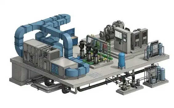
Mechanical BIM modeling is the 3D modeling of heating, ventilation, air conditioning and mechanical piping systems inside BIM software such as Revit. Each component holds real data, including duct size, airflow, pipe diameter, insulation, material and equipment capacity, so the model can be coordinated, scheduled and used to produce drawings.
Mechanical drafting
The 2D production side: plans, sections, elevations and details. When drawings are drawn by hand in CAD, someone has to remember to change each one.
A mechanical BIM model
When drawings are generated from the model, a change to a duct size updates every sheet — and systems can be clash-checked, counted, scheduled and handed over.
Scope
Where Mechanical Modeling Gets Hard
Space And Clearances
Ducts with insulation and liner get bigger than they look. We model insulation thickness, hangers and service clearances, then check coil pull space, filter access, valve access and controls.
01
Pipe Slope And Elevation
Condensate, drains, steam and hydronic mains need proper pitch and air vents at high points. Slopes are modeled and checked, not assumed.
02
Structure And Penetrations
Every duct and pipe that passes through a beam, slab or rated wall needs an opening. We locate them early and report to the structural and architectural teams before concrete is poured or steel is fabricated.
03
Design Changes
Mechanical design moves constantly during construction documents. We track revisions with clouds and a log, so your team can see exactly what changed.
04
Mechanical Systems We Model
- Supply, return, exhaust and outside air ductwork in rectangular, round and flat-oval
- Air handling units, rooftop units, fan coil units, VAV and CAV boxes, energy recovery units and exhaust fans
- Chilled water, hot water, condenser water, glycol and steam piping
- Boiler plants, chiller plants, cooling towers, pumps, heat exchangers and expansion tanks
- Refrigerant piping for VRF, VRV and split systems
- Diffusers, grilles, louvers, dampers, fire dampers and access doors
- Kitchen exhaust, lab exhaust and process ventilation
- Kitchen exhaust, lab exhProcess piping and industrial mechanical systemsaust and process ventilation
Our Mechanical Drafting Services
- Mechanical floor plans and roof plans
- Equipment layouts and mechanical room plans and sections
- Detail sheets for connections, supports and equipment installation
- Permit drawing sets and as-built drawings from redlines
- Equipment and air device schedules
Not every job needs a full model. Sometimes you need good drawings on time. Our drafters produce mechanical plans, sections, details, riser diagrams, schedules and legends in AutoCAD, AutoCAD MEP or Revit, following the National CAD Standard and your firm’s layers, title blocks and annotation style. We deliver PDF and DWG, and Revit files when the project is model-based.
Levels of development
Levels Of Development For Mechanical Models
We follow the BIMForum Level of Development specification, which most US projects use, and agree the LOD for each system in writing before modeling starts.
LOD | Mechanical Content | When To Use |
|---|---|---|
LOD 200 | Approximate duct and pipe routes, equipment as placeholders | Early design, budgeting, space planning |
LOD 300 | Accurate sizes and locations, connected systems, insulation shown | Coordination and permit documentation |
LOD 350 | Adds supports, fittings and interfaces with other trades | Detailed trade coordination |
LOD 400 | Fabrication-ready fittings, joints, hangers and assembly details | Shop drawings, sheet metal and pipe fabrication |
LOD 500 | Field-verified as-built model | Closeout and facility management |
Compliance
US Codes And Standards Behind Our Work
We work to what is shown on your design documents and the standards that normally govern mechanical work in the United States. Sizing and design decisions stay with your engineer of record. Our role is to model accurately and tell you early when something doesn’t fit.
- ASHRAE 62.1 ventilation and ASHRAE 90.1 energy requirements as reflected in the design
- International Mechanical Code (IMC) and local amendments
- SMACNA HVAC duct construction standards
- NFPA 90A for air conditioning and ventilating systems and NFPA 96 for commercial kitchen exhaust
- ASME B31.9 piping principles for building services piping
- California Title 24 and other state energy requirements where applicable
Our process
From intake to issue
Six steps from first drawing review to final delivery — with revisions tracked in a clear log and rolled into the model every cycle.
Step 1
Review
Drawings, specs, equipment schedules and BIM Execution Plan — we confirm scope and dates before modeling starts.
Step 2
Setup
Template, linked models, levels, grids and system naming aligned to your project standards.
Step 3
Modeling
Equipment first, then mains, then branches and terminals — production by system and level.
Step 4
Coordination Check
Internal clash pre-check against architectural, structural, electrical, plumbing and fire protection.
Step 5
Drafting
Sheets, schedules and details produced directly from the model.
Step 6
QA/QC And Delivery
Standards check, sheet review and issue — with revisions tracked in a clear log.
What you receive
- Coordinated Revit mechanical model and Navisworks files
- Mechanical plans, sections, details and schedules in PDF and DWG
- Quantity takeoffs for ducts, pipes, fittings, insulation and equipment
- Fabrication drawings where LOD 400 is in scope
- As-built mechanical drawings after site verification
- A list of assumptions, RFIs and open items
Who We Work With
- Mechanical design drawings, equipment schedules and specifications (RVT, DWG or PDF)
- Architectural and structural models or drawings for coordination
- Your BIM Execution Plan, or our help drafting one
- Preferred Revit or AutoCAD version, template and title blocks
- Required LOD by system, deliverables and due dates
- Any approved equipment submittals already available
Software & tools
Our platform stack
Autodesk Revit
Navisworks Manage
AutoCAD / AutoCAD MEP
Autodesk Construction Cloud & BIM 360
Revit is our default on new projects; we also handle AutoCAD and AutoCAD MEP drafting for projects that haven’t moved to BIM.
Cost is driven by building area, system density, the LOD you need, whether drawings are included and how many design revisions come during the job. Plant rooms and hospital air systems take longer than open office floors — send us your drawings and we’ll give you a fixed price or an hourly estimate with the assumptions written down.
Engagement & cost
Engagement options
Fixed price per project
A scoped quote with assumptions spelled out, so there are no surprises later.
Hourly
For flexible or fast-moving scopes that change from week to week.
Dedicated team
Modelers who work as an extension of your office, in your standards.
Industries & project types
Where our mechanical models get built
- Hospitals, labs and healthcare facilities with tight air-change and pressure requirements
- Commercial offices, retail and hospitality
- Schools and universities03
- Industrial plants, warehouses and cold storage
- Data centers and mission-critical facilities
- Multifamily and mixed-use buildings06
- Central utility plants and energy retrofits
We work with mechanical contractors, sheet metal shops, HVAC design-build firms, mechanical and MEP engineers, general contractors, construction managers and owners’ representatives. If your in-house team is stretched, we slot in as an extension of it and follow your workflows.
Why BIMACME
Why choose Bimacme for mechanical BIM
If you have outsourced mechanical modeling before, you know the risks: slow replies, drifting standards, models you have to rebuild. We set things up to avoid that.
- Team comfortable in both Revit and AutoCAD, so you're not forced into one workflow
- Insulation, access and clearances modeled from the start
- Duct and pipe assemblies that can move straight into prefabrication
- Flexible engagement: per project, hourly or dedicated resource
- Clear reporting and quick replies during coordination weeks
- Mechanical modeling and drafting under one roof
FAQ
Frequently Asked Questions
Still have a question about scope, standards, or staffing? Our team will answer within one US business day.
What Is The Difference Between Mechanical Drafting And Mechanical BIM Modeling?
Drafting produces 2D drawings. BIM modeling builds a 3D, data-rich model and generates the drawings from it. Modeling takes more setup but saves time on coordination and revisions.
Do You Work In Revit Only Or AutoCAD As Well?
Both. Revit is our default on new projects. We also handle AutoCAD and AutoCAD MEP drafting for clients and projects that haven’t moved to BIM.
Can You Model Mechanical Systems From PDF Drawings?
Yes. We model from PDFs, note our assumptions and raise RFIs for unclear items.
Do You Follow SMACNA Standards For Ductwork?
Yes. Duct construction, joints, reinforcement and fittings follow SMACNA unless your specifications say otherwise.
Can You Model Mechanical Rooms And Central Plants?
Yes. Equipment, piping, valves, supports, housekeeping pads and service clearances are all modeled so that tight plant rooms can be coordinated.
Do You Provide Fabrication-Ready Drawings?
Yes, at LOD 400. See our MEP shop drawings and prefabrication modeling services for detail.
How Fast Can You Start?
Usually within a few working days once we have your drawings and scope.
What Files Will I Receive?
Native RVT files, NWC files for Navisworks, PDF sheets and DWG exports, based on the scope we agree.
Need mechanical modeling or drafting support this month?
Send us your drawings and we’ll come back with scope, timeline and pricing usually within two business days.